Massage wand modification
Spoiler: it ain't used for massage
What do you do with a waterlogged massage wand? Mod it into an Arduino-controlled bluetooth vibrator with optional Websocket command relay, of course!
I completed this project back in 2020, but never got around to writing about it. So here it is!
This article will cover my process of disassembling the original device and modding it with my custom electronics. For more details about the parts of this project that are not enclosed inside the wand, see the associated project page.
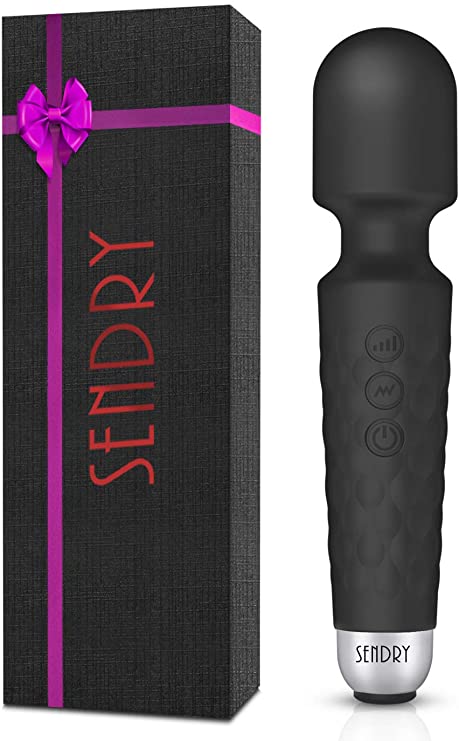
The original device
This is the original wand I had. For $20, it’s a pretty decent piece of hardware: multiple modes, decent power, very inexpensive.
However, it became waterlogged one day back in the summer of 2020 due to being accidentally included in the washing machine.
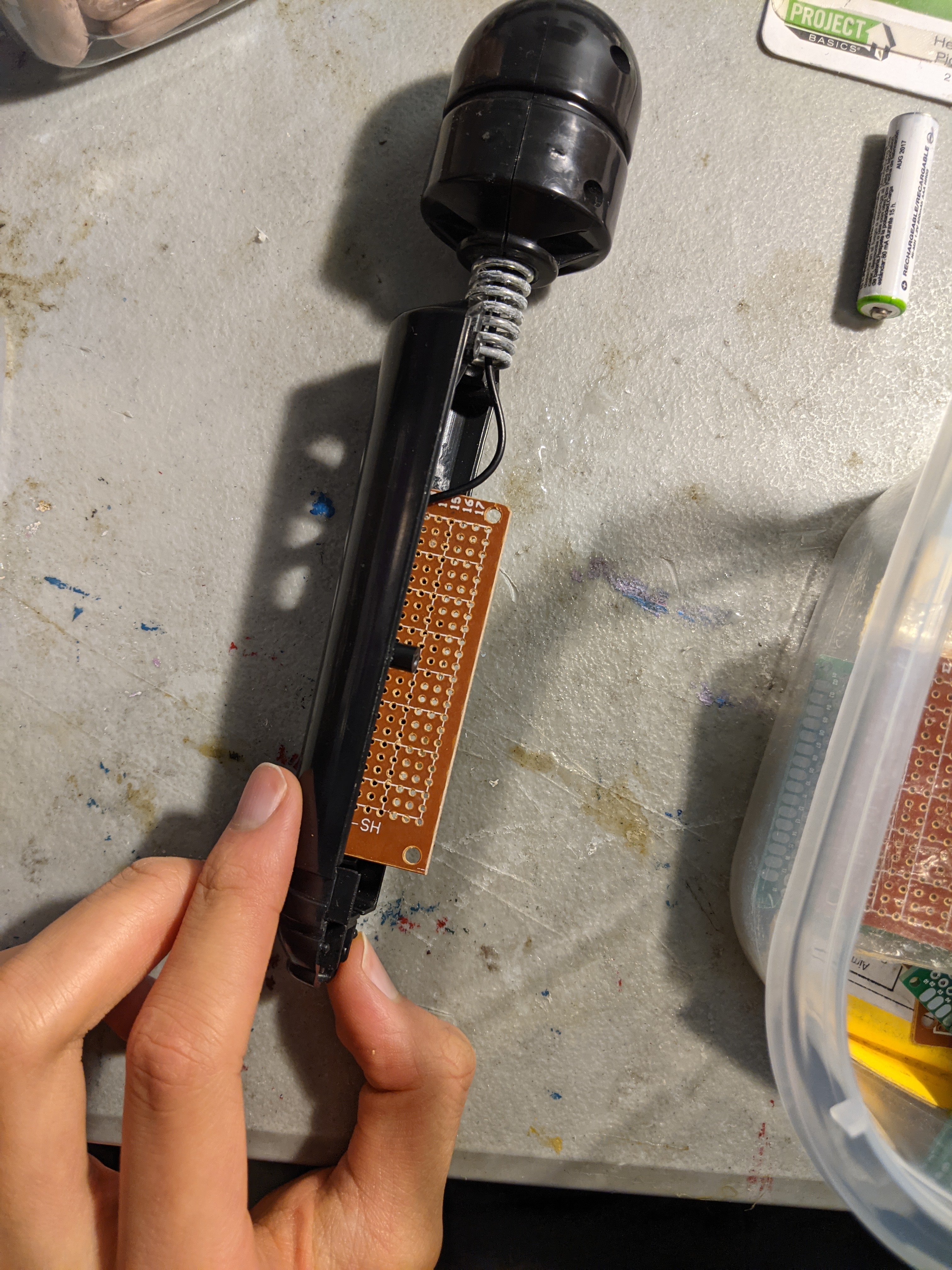
Once I got home from the apartment I had during my summer internship, around August 2020 I opened up the device to let it dry.
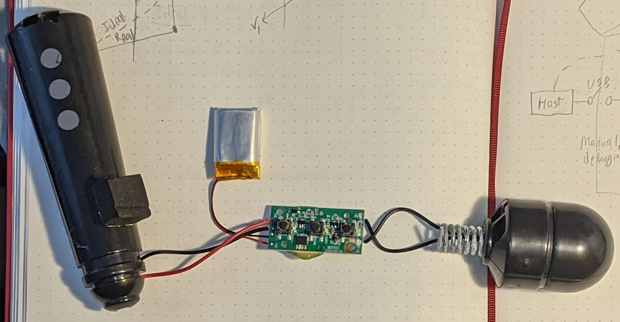
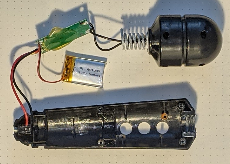
The internals are frankly quite boring but that gave me an idea: what if I just swapped out the circuit board with my own?
Ambitious First Idea
From October to November 2020 I tried my hand at designing a new circuit for this wand. I had a (way-too-ambitious) set of requirements for a new circuit for this vibrator:
- Can act as a drop-in replacement for the old circuit without hardware modification
- Can communicate over Bluetooth and Wifi (via ESP32)
- The existing button slots can be used to interface with it
- Uses the original Li-ion battery for charge and discharge
- Can be charged via the original plug
- Has a capacitive sensor on the head for detecting the user
Here is the KiCAD schematic I designed that meets all of these specifications!

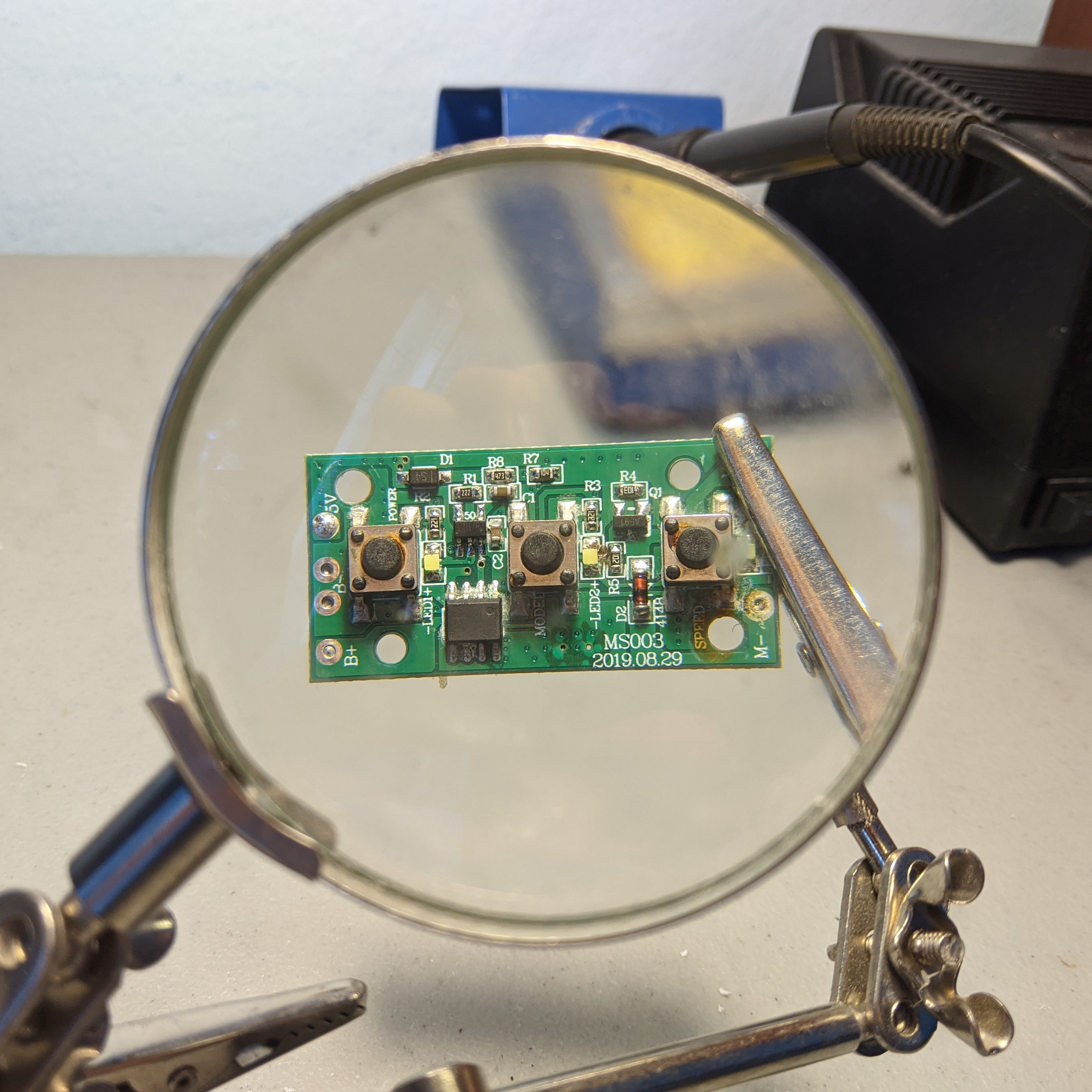
PCB Measurement
I additionally desoldered the central circuit to measure dimensions of the holes and buttons so I could lay out the components on a PCB.


Here are the 3D renderings of the replacement PCB I created from the schematic and reference drawing.

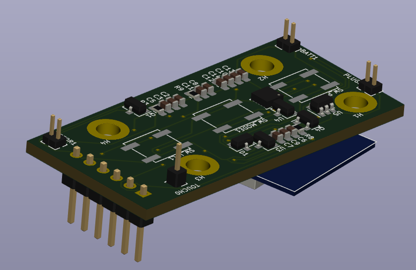
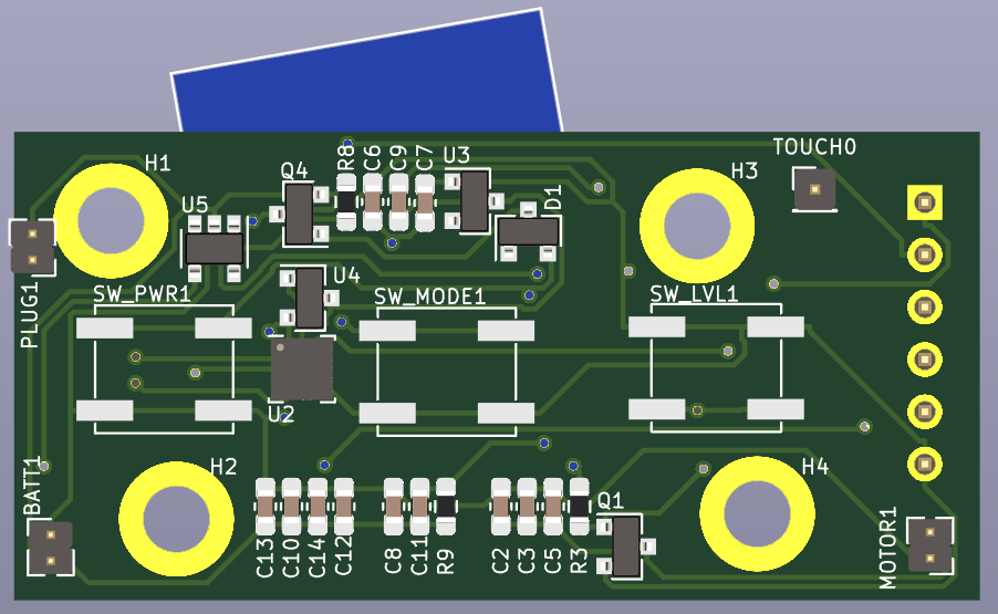

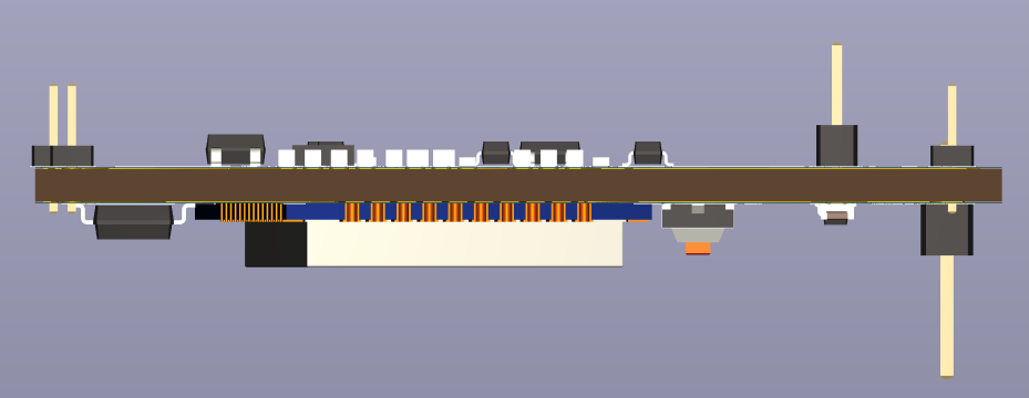
Yes, that ESP32 is slanted. Otherwise, it would end up overlapping with the drill holes!
Postmortem
This design is obviously extremely ambitious, and it’s a fairly complex circuit. I constantly agonized over whether or not all the connections were accounted for, and whether or not all the capacitors and resistors were correct, so I ended up never ordering the PCB or carrying out this plan.
Janky Pragmatic Second Idea
In December, I was fed up with not having a functional massage wand for so long, so I just decided to make something simple. This time, I greatly cut down on my requirements:
- Can communicate over Bluetooth (via HC-05)
- Can accept power from Li-Ion battery via external XT60 connector
- Can control motor
Essentially, this was a completely headless device that would only work if it was connected to Bluetooth. But that’s fine, because so long as I can connect to it, it works.
Sizing the board
I had an Arduino Pro Mini clone lying around that had been used for a previous project, but was no longer used. It was soldered directly to a perfboard (no headers for replaceability, no nothing) so I couldn’t find a good repurposing for it for a while. Thankfully, this project came along and gave it a use!
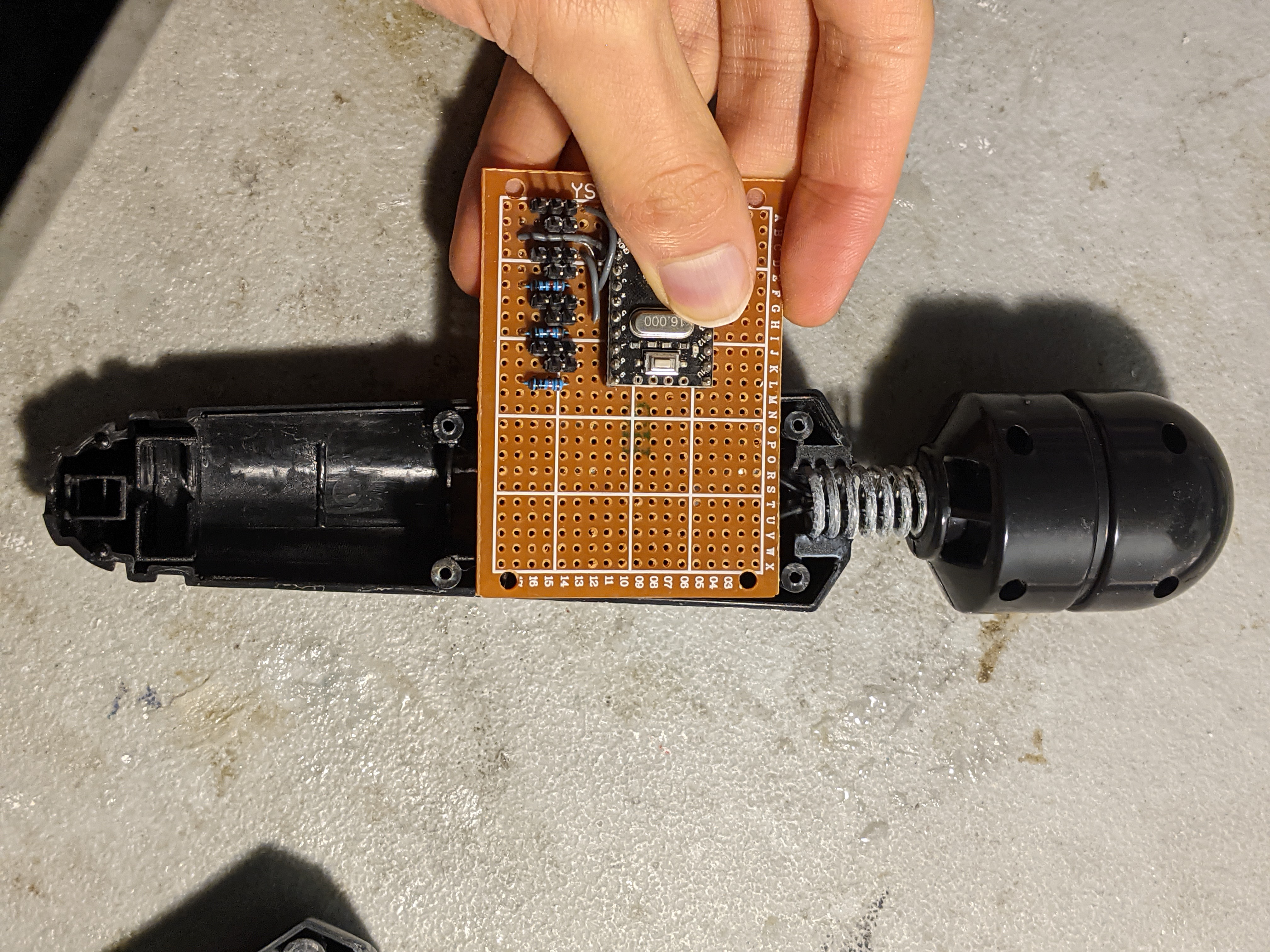
I cut the board in half lengthwise around the Arduino, disconnecting and desoldering the old wires.
Soldering the board
I had an HC-05 from a different project as well, that was no longer in use. So, I desoldered it off of the headers binding it to the old project.

However, I did need to attach it to my new board, and unfortnately it’s a rather long module so I had to make some… slight aesthetic compromises to the board.
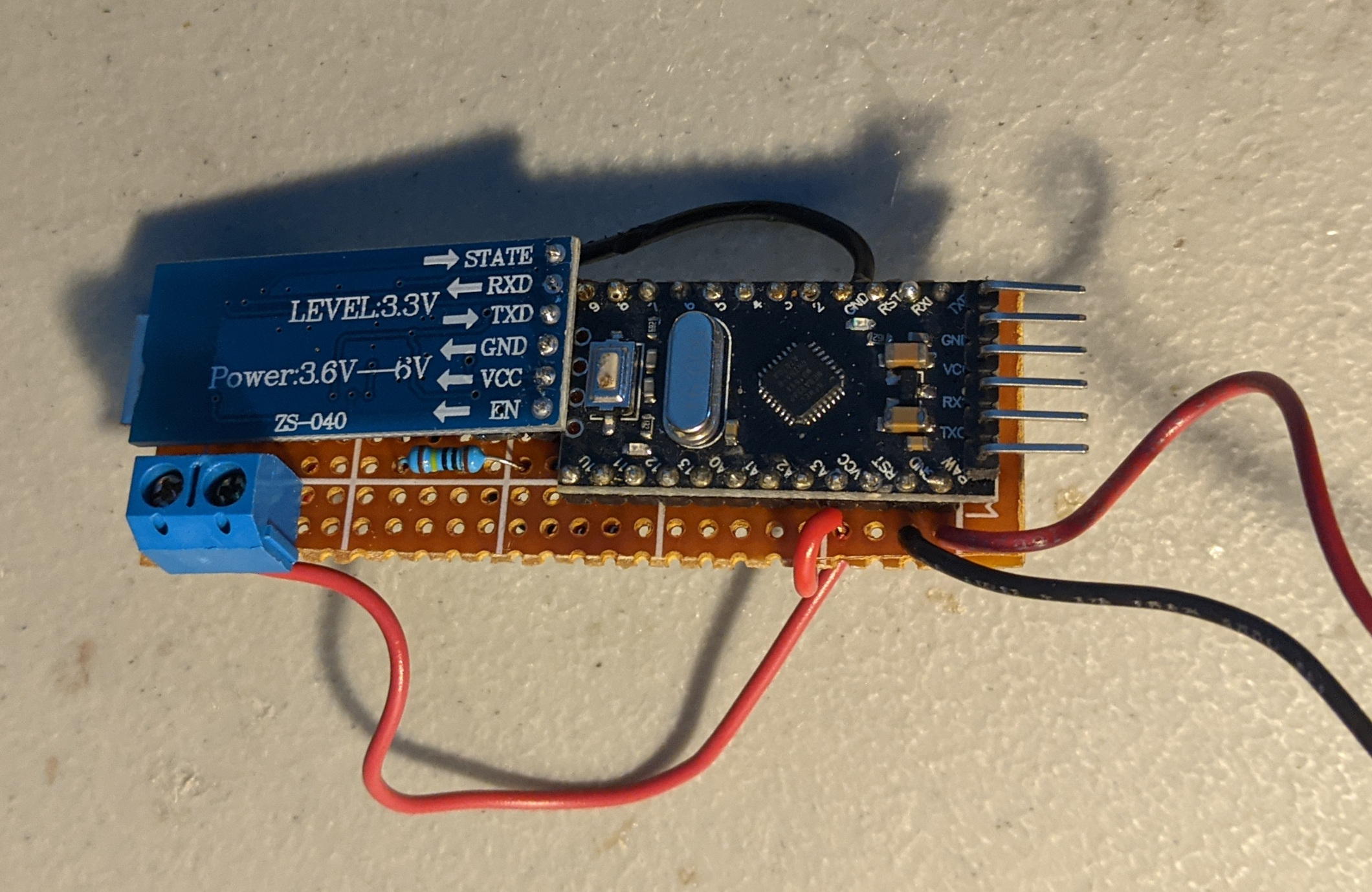
Additionally, because the MOSFET couldn’t fit in a conventional location, I had to make some “compromises” there as well.

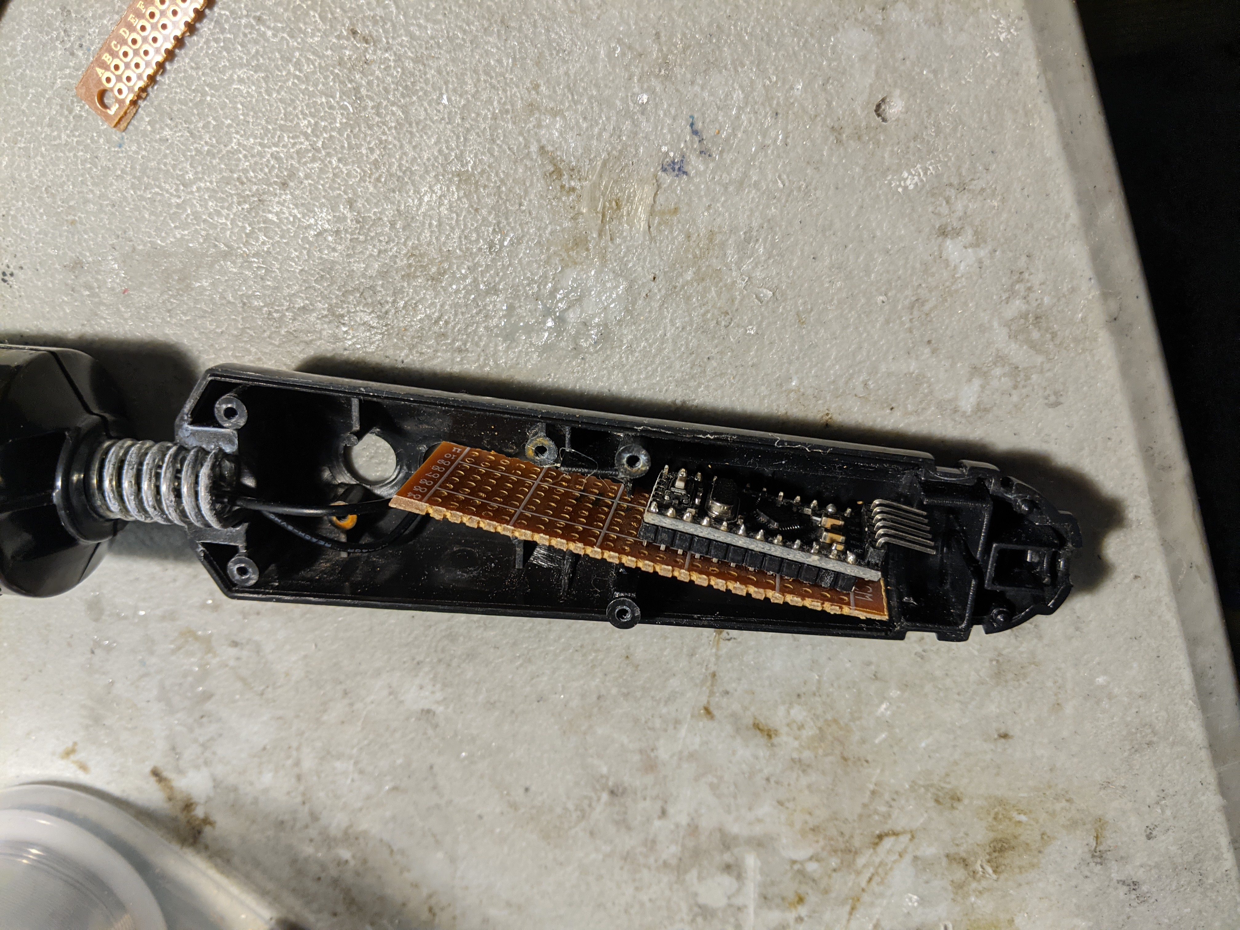
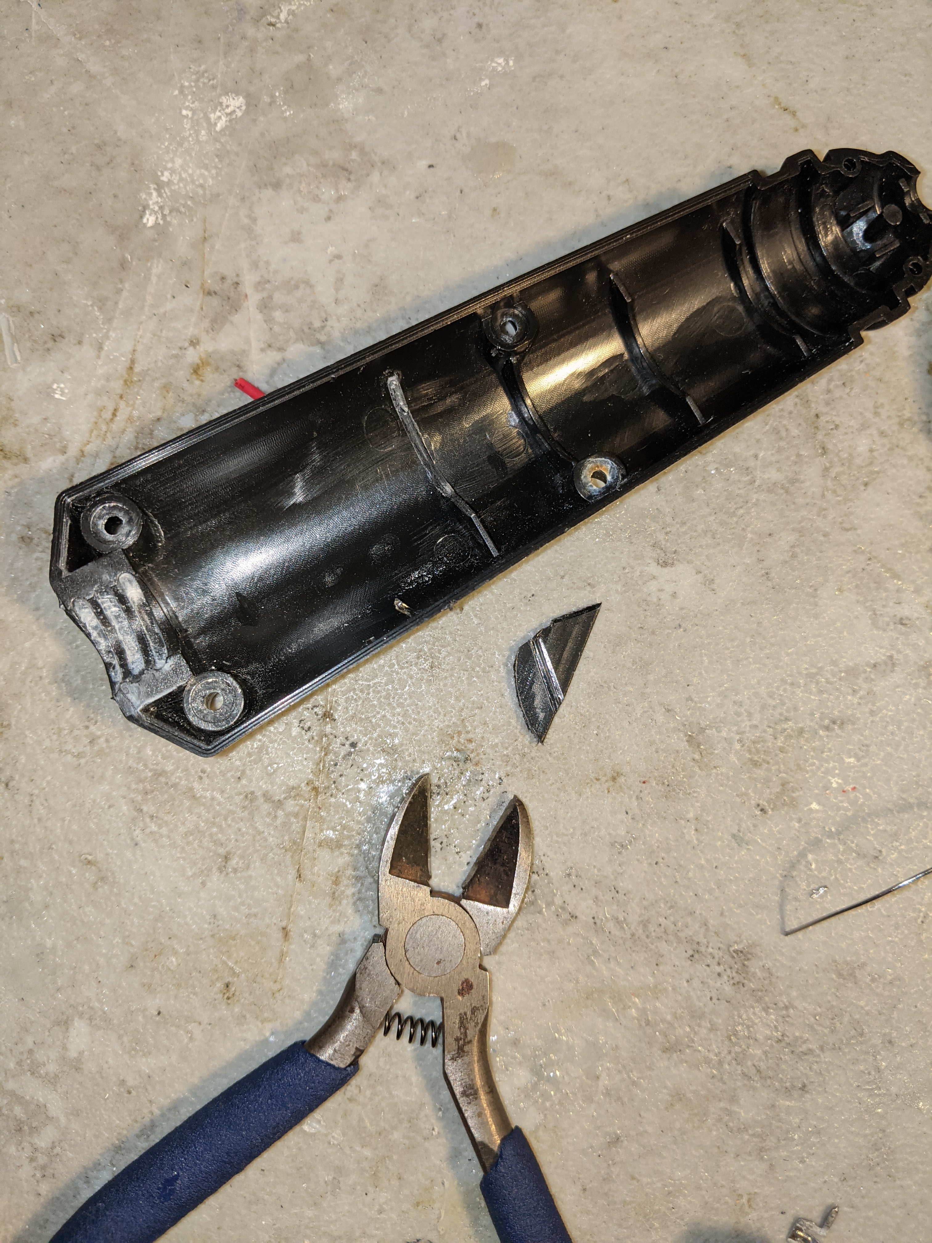
Furthermore, there was not enough vertical clearance for the board if you tried to encase this circuit inside the chassis.
So, I had to destructively modify the case with a wire cutter.
Once that was all done, all I had to do was solder the PCB to the motor, and I was done!

Results
This device is almost a direct upgrade from the previous one.
- You can control it with a phone via Bluetooth connection! With other services involved, someone else can even control it (or dare I say, command it) from anywhere in the world via a Websocket relay! See the project page for more details about that. The uses of this relay system are as of yet unclear.
- Double the voltage means double the motor power!
There are a few drawbacks, however.
- The silicone exterior could not be directly slipped back on. I had to cut an opening through it, so it no longer protects the electronics from the external environment. To operate it in an environment with fluids, it must be wrapped in plastic wrap.
- The external battery makes it bulkier, but that’s the price you pay for double the power.